

")

")


[ad_1]
There are more than a few strategies of visualizing 3-dimensional gadgets in two-dimensional house. As an example, maximum three-D graphics engines use viewpoint projection as the principle type of projection. It is because viewpoint projection is a superb illustration of the true global, wherein gadgets develop into smaller with expanding distance. But if the relative place of gadgets isn’t vital, and for a greater working out of the scale of gadgets, you’ll be able to use parallel projections. They’re extra commonplace in engineering and structure, the place you will need to care for parallel traces. Because the start of laptop graphics, those projections were used to render three-D scenes when three-D rendering {hardware} acceleration was once no longer imaginable. Just lately, more than a few types of parallel projections have develop into a method selection for virtual artists, and they’re used to show gadgets in infographics and in virtual artwork normally.
The aim of this newsletter is to turn easy methods to create and manipulate isometric perspectives in SVG and easy methods to outline those gadgets the use of, specifically, the JointJS library. For instance SVG’s functions in developing parallel projections, we will be able to use isometric projection for instance. This projection is among the dominant projection varieties as it means that you can care for the relative scale of gadgets alongside all axes.
Isometric Projection
Let’s outline what isometric projection is. Initially, this can be a parallel form of projection wherein all traces from a “digital camera” are parallel. It implies that the size of an object does no longer rely at the distance between the “digital camera” and the thing. And in particular, in isometric (this means that “equivalent measure” in Greek) projection, scaling alongside every axis is similar. That is accomplished via defining equivalent angles between all axes.
Within the following symbol, you’ll be able to see how axes are situated in isometric projection. Remember the fact that on this article, we will be able to be the use of a left-handed coordinate gadget.

Some of the options of the isometric projection is that it may be deconstructed into 3 other 2D projections: most sensible, facet, and entrance projections. As an example, a cuboid can also be represented via 3 rectangles on every 2D projection after which mixed into one isometric view. The following symbol represents separate projections of an object the use of the left-handed coordinate gadget.
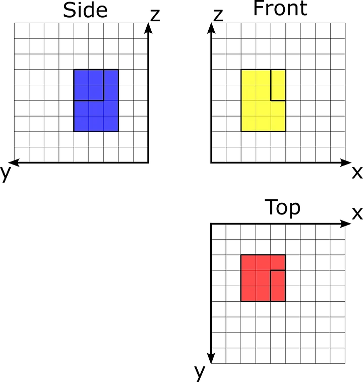
Separate perspectives of the orthographic projection
Then, we will be able to mix them into one isometric view:
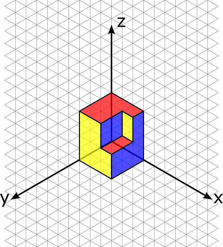
Isometric view of the instance object
The problem with SVG is that it comprises 2D gadgets which can be positioned on one XY-plane. However we will be able to conquer this via combining all projections in a single aircraft after which one by one making use of a metamorphosis to each object.
SVG Isometric View Transformations
In three-D, to create an isometric view, we will be able to transfer the digital camera to a undeniable place, however SVG is solely a 2D structure, so we need to create a workaround to construct one of these view. We advise studying Cody Walker’s article that items a technique for developing isometric representations from 2D object perspectives — most sensible, facet, and entrance projections. According to the thing, we want to create transformations for every 2D projection of the thing one by one.
First, we want to rotate our aircraft via 30 levels. After which, we will be able to skew our 2D symbol via -30 levels. This variation will align our axes with the axes of the isometric projection.
Then, we want to use a scale operator to scale our 2D projection down vertically via 0.8602. We want to do it because of the reality of isometric projection distortion.
Let’s introduce some SVG options that can lend a hand us put in force isometric projection. The SVG specification lets in customers to specify a specific transformation within the turn into characteristic of an SVG detail. This characteristic is helping us practice a linear transformation to the SVG detail. To turn into 2D projection into an isometric view, we want to practice scale, rotate, and skew operators.
To constitute the transformation in code, we will be able to use the DOMMatrixReadOnly object, which is a browser API, to constitute the transformation matrix. The use of this interface, we will be able to create a matrix as follows:
const isoMatrix = new DOMMatrixReadOnly()
    .rotate(30)
    .skewX(-30)
    .scale(1, 0.8602);
This interface lets in development a metamorphosis matrix the use of our values, after which we will be able to practice the ensuing price to theturn into characteristic the use of the matrix serve as.
In SVG, we will be able to provide just one 2D house at a time, so for our conversion, we will be able to be the use of most sensible projection as a base projection. That is most commonly as a result of axes on this projection correspond with axes in a standard SVG viewport.
To display SVG probabilities, we will be able to be the use of the JointJS library. We outlined an oblong grid within the XY-plane with a cellular width of 20. Let’s outline SVG for the weather at the most sensible projection from the instance. To correctly render this object, we want to specify two polygons for 2 ranges of our object. Additionally, we will be able to practice a translate transformation for our detail in 2D house the use of DOMMatrix:
// Translate transformation for Top1 Part
const matrix2D = new DOMMatrixReadOnly()
    .translate(200, 200);
<!--Top1 element-->
<polygon joint-selector="frame" identity="v-4"
stroke-width="2" stroke="#333333" fill="#ff0000"
fill-opacity="0.7" issues="0,0 60,0 60,20 40,20 40,60 0,60"
turn into="matrix(1,0,0,1,200,200)">
</polygon>
<!--Top2 element-->
<polygon joint-selector="frame" identity="v-6"
stroke-width="2" stroke="#333333" fill="#ff0000"
fill-opacity="0.7" issues="0,0 20,0 20,40 0,40"
turn into="matrix(1,0,0,1,240,220)">
</polygon>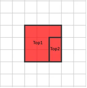
Then, we will be able to practice our isometric matrix to our components. Additionally, we will be able to upload a translate transformation to put components in the correct position:
const isoMatrix = new DOMMatrixReadOnly()
    .rotate(30)
    .skewX(-30)
    .scale(1, 0.8602);

const top1Matrix = isoMatrix.translate(200, 200);
const top2Matrix = isoMatrix.translate(240, 220);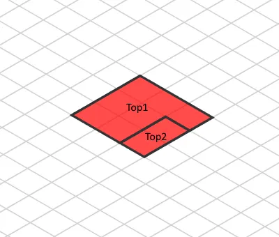
Isometric view with out top adjustment
For simplicity, let’s think that our detail’s base aircraft is positioned at the XY aircraft. Due to this fact, we want to translate the highest view so it’s going to be considered as it’s positioned at the most sensible of the thing. To do it, we will be able to simply translate the projection via its Z coordinate at the scaled SVG house as follows. The Top1 detail has an elevation of 80, so we will have to translate it via (-80, -80). In a similar fashion, the Top2 detail has an elevation of 40. We will be able to simply practice those translations to our present matrix:
const top1MatrixWithHeight = top1Matrix.translate(-80, -80);
const top2MatrixWithHeight = top1Matrix.translate(-40, -40);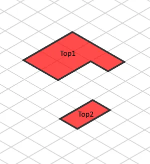
Ultimate isometric view of most sensible projection
After all, we will be able to have the next turn into attributes for Top1 and Top2 components. Be aware that they fluctuate simplest within the two closing values, which constitute the translate transformation:
// Top1 detail
turn into="matrix(0.8660254037844387,0.49999999999999994,-0.8165000081062317,0.47140649947346464,5.9,116.6)"

// Top2 detail
turn into="matrix(0.8660254037844387,0.49999999999999994,-0.8165000081062317,0.47140649947346464,26.2,184.9)"
To create an isometric view of facet and entrance projections, we want to make a web so we will be able to position all projections on 2D SVG house. Let’s create a web via attaching facet and entrance perspectives very similar to the vintage dice web:
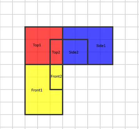
Then, we want to skewX facet and entrance projections via 45 levels. It’ll let us align the Z-axis for all projections. After this modification, we will be able to get the next symbol:
Ready 2D projection
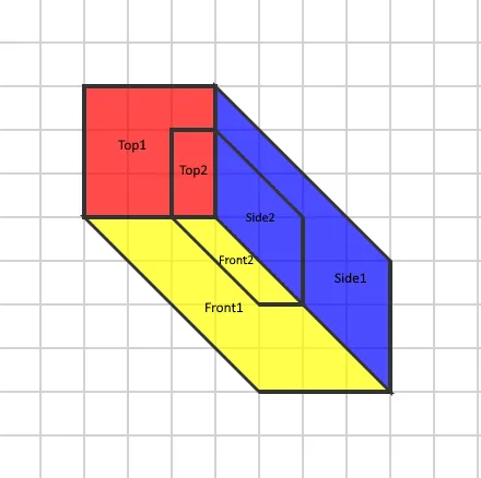
Then, we will be able to practice our isoMatrix to this object:

Isometric projection with out intensity adjustments
In each projection, there are portions that experience a distinct third coordinate price. Due to this fact, we want to alter this intensity coordinate for each projection as we did with the highest projection and its Z coordinate. After all, we will be able to get the next isometric view:
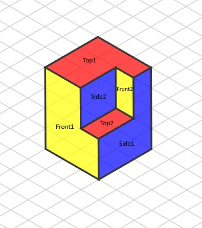
Ultimate isometric view of the thing
The use of JointJS for the Isometric Diagram
JointJS lets in us to create and manipulate such gadgets conveniently because of its components framework and extensive set of equipment. The use of JointJS, we will be able to outline and keep an eye on isometric gadgets to construct robust isometric diagrams.
Take note the elemental isometric transformation from the start of the thing?
const isoMatrix = new DOMMatrixReadOnly()
    .rotate(30)
    .skewX(-30)
    .scale(1, 0.8602);
Within the JointJS library, we will be able to practice this modification to the entire object which retail outlets all SVG components, after which merely practice the object-specific transformations on most sensible of this.
Isometric Grid Rendering
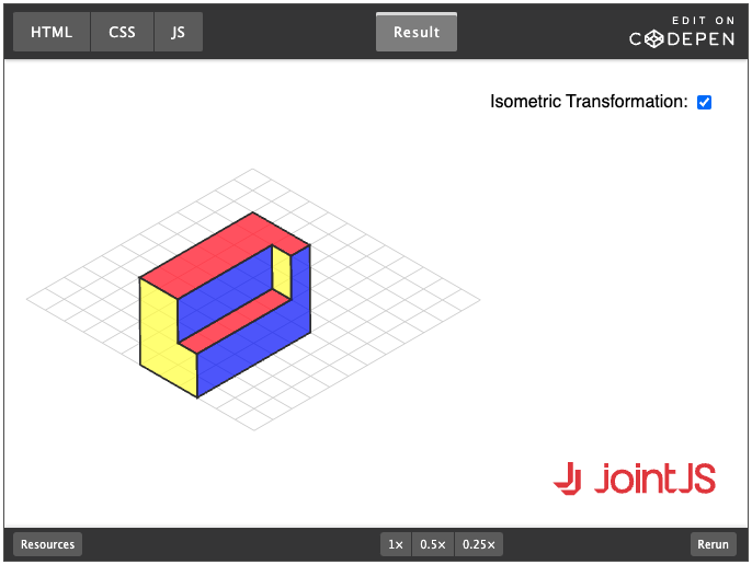
JointJS has nice functions within the rendering of customized SVG markup. Using JointJS, we will be able to generate a trail this is aligned to an untransformed grid and feature it reworked mechanically with the grid, because of the worldwide paper transformation that we discussed up to now. You’ll be able to see the grid and the way we interpret the coordinate gadget within the demo underneath. Be aware that we will be able to dynamically trade the paper transformation, which permits us to switch the view at the fly:

Making a Customized Isometric SVG Part
Right here, we display a customized SVG Isometric form in JointJS. In our instance, we use the isometricHeight assets to retailer details about a 3rd size after which use it to render our isometric object. The next snippet presentations how you’ll be able to name the customized createIsometricElement serve as to change object homes:
const detail = createIsometricElement({
isometricHeight: GRID_SIZE * 3,
dimension: { width: GRID_SIZE * 3, top: GRID_SIZE * 6 },
place: { x: GRID_SIZE * 6, y: GRID_SIZE * 6 }
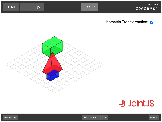
});Within the following demo, you’ll be able to see that our customized isometric detail can also be moved like an odd detail at the isometric grid. You’ll be able to trade dimensions via changing the parameters of the createIsometricElement serve as within the supply code (while you click on “Edit on CodePen”):
Z-Index Calculation in Isometric Diagrams
Some of the issues of an isometric view is striking components respective to their relative place. In contrast to in a 2D aircraft, in an isometric view, gadgets have perceived top and can also be positioned one in the back of the opposite. We will be able to accomplish that conduct in SVG via striking them into the DOM in the correct order. To outline the order in our case, we will be able to use the JointJS z characteristic, which permits sending the right kind detail to the background in order that it may be overlapped/hidden via the opposite detail as anticipated. You’ll be able to in finding extra details about this downside in an excellent article via Andreas Hager.
We determined to type the weather the use of the topological sorting set of rules. The set of rules is composed of 2 steps. First, we want to create a different graph, after which we want to use a depth-first seek for that graph to search out the right kind order of components.
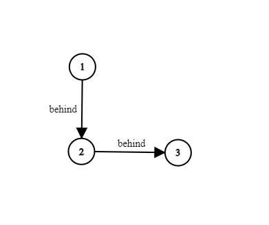
As step one, we want to populate the preliminary graph — for every object, we want to in finding all gadgets in the back of it. We will be able to do this via evaluating the positions in their backside aspects. Let’s illustrate this step with photographs — let’s, as an example, take 3 components which can be situated like this:
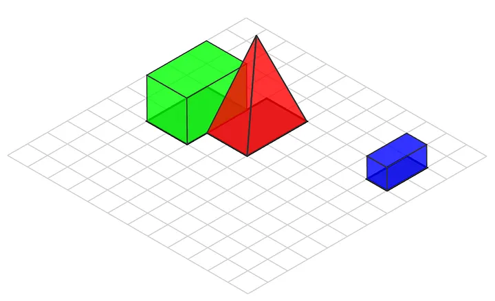
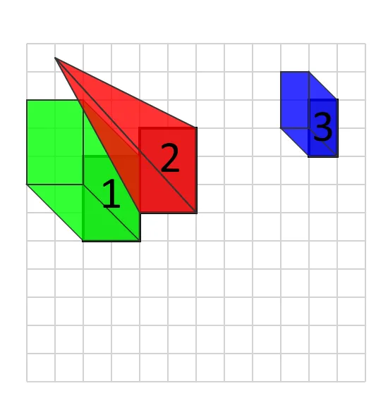
We now have marked the ground facet of every object in the second one symbol. The use of this information, we will be able to create a graph construction that can style topological family members between components. Within the symbol, you’ll be able to see how we outline the issues at the backside facet — we will be able to in finding the relative place of all components via evaluating aMax and bMin issues. We outline that if the x and y coordinates of level bMin are not up to the coordinates of level aMax , then object b is positioned in the back of object a.
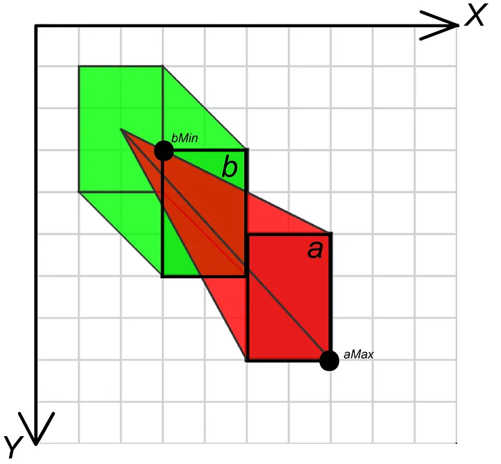 Set of rules knowledge in a 2D house
Evaluating the 3 components from our earlier instance, we will be able to produce the next graph:
Topological graph
After that, we want to use a variation of the depth-first seek set of rules to search out the right kind rendering order. A depth-first seek lets in us to talk over with graph nodes consistent with the visibility order, ranging from probably the most far away one. Here’s a library-agnostic instance of the set of rules:
const sortElements = (components: Rect[]) => {
    const nodes = components.map((el) => {
        go back {
            el: el,
            in the back of: [],
            visited: false,
            intensity: null,
        };
    });

    for (let i = 0; i < nodes.duration; ++i) {
        const a = nodes[i].el;
        const aMax = aBBox.bottomRight();

        for (let j = 0; j < nodes.duration; ++j) {
            if (i != j) {
                const b = nodes[j].el;
                const bMin = bBBox.topLeft();
                if (bMin.x < aMax.x && bMin.y < aMax.y) {
                    nodes[i].in the back of.push(nodes[j]);
                }
            }
        }
    }

    const sortedElements = depthFirstSearch(nodes);
    go back sortedElements;
};

const depthFirstSearch = (nodes) => {
    let intensity = 0;
    let sortedElements = [];

    const visitNode = (node) => {
        if (!node.visited) {
            node.visited = true;

            for (let i = 0; i < node.in the back of.duration; ++i) {
                if (node.in the back of[i] == null) {
                    smash;
                } else {
                    visitNode(node.in the back of[i]);
                    delete node.in the back of[i];
                }
            }

            node.intensity = intensity++;
            sortedElements.push(node.el);
        }
    };

    for (let i = 0; i < nodes.duration; ++i) {
        visitNode(nodes[i]);
    }

    go back sortedElements;
};
This system can also be carried out simply the use of the JointJS library — within the following CodePen, we use a different JointJS tournament to recalculate z-indexes of our components every time the location of a component is modified. As defined above, we use a different z assets of the detail style to specify rendering order and assign it all through the depth-first traversal. (Be aware that the set of rules’s conduct is undefined relating to intersecting components because of the character of the implementation of isometric gadgets.)
The JointJS Demo
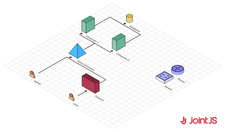
We now have created a JointJS demo that mixes all of those strategies and strategies and in addition means that you can simply transfer between 2D and isometric SVG markup. Crucially, as you’ll be able to see, the robust options of JointJS (which permit us to transport components, attach them with hyperlinks, and create equipment to edit them, amongst others) paintings simply as neatly within the isometric view as they do in 2D.
You’ll be able to see the demo right here.
All through this newsletter, we used our open-source JointJS library for representation. Alternatively, because you had been so thorough together with your exploration, we wish to lengthen to you a call for participation to our no-commitment 30-day trial of JointJS+, a complicated business extension of JointJS. It’ll assist you to enjoy further robust equipment for developing pleasant diagrams.
[ad_2]


